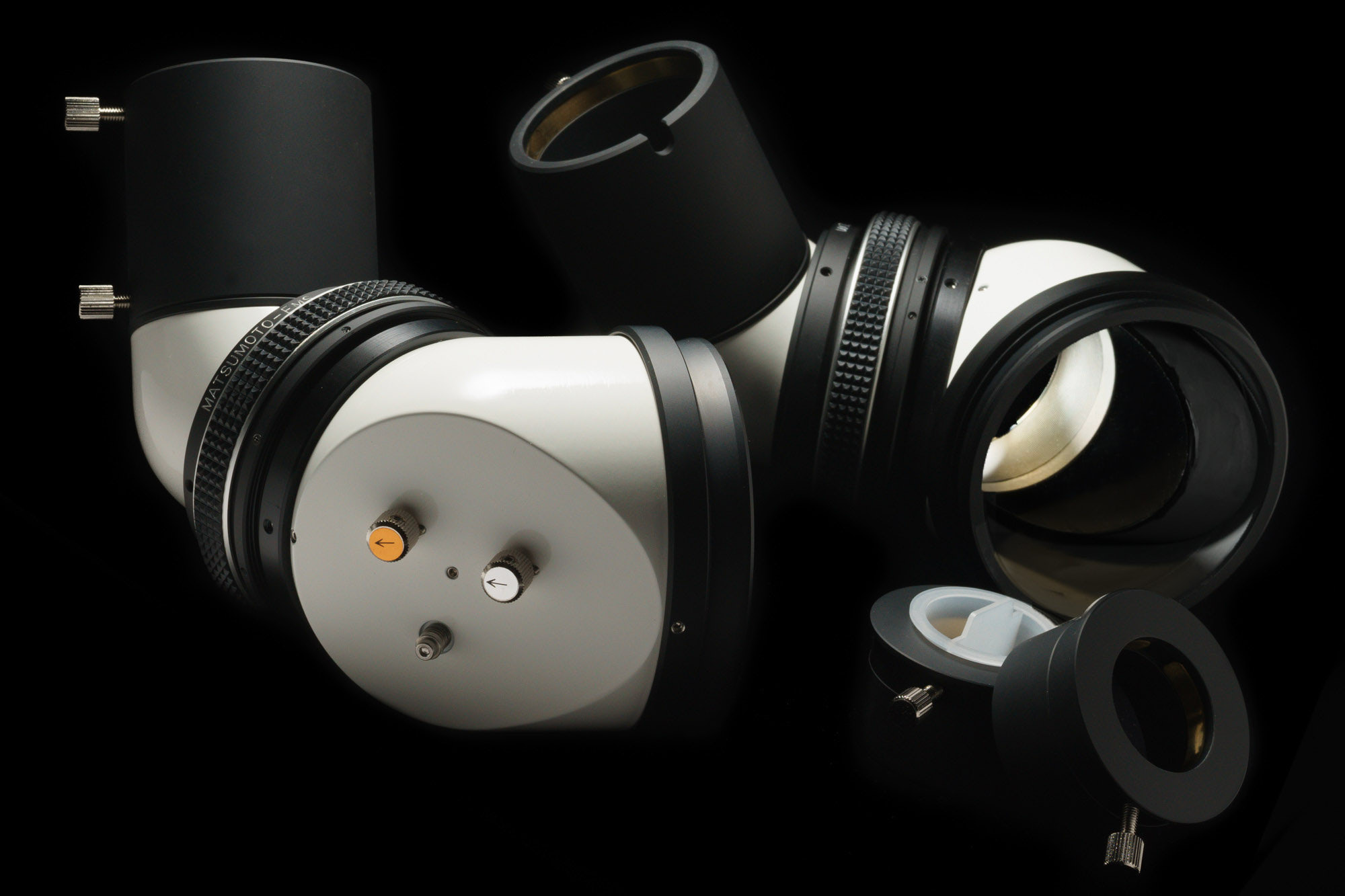
The photo is the customized EMS-L for the binocular use.
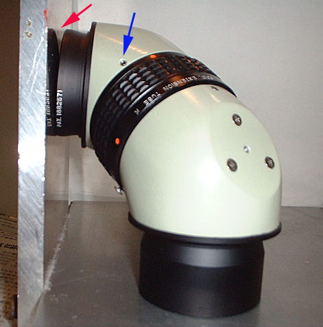
Put the EMS on the right-angle gauge. (A desktop and a wall can be a substitute.) You see the eye-side surface doesn’t touch the wall closely.(red arrow)
Then,unscrew the three set-screws (blue arrow in the photo) and fix the connecting angle untill the both sides of the EMS will touch the floor and the wall.
(The place of the three set-screws are different from the types of the EMS. Please consult me when you cannot identify the screws.)
直角面定規(机面と壁面等が代用できます)にEMSを載せます。
この写真では、接眼側の端面が垂直面に密着していません。
第2ミラー(接眼側)の3ヶ所のセットビス(青い矢印)を緩め、
両端面がそれぞれ水平面と垂直面に密着するようにします。
This photo is the finished stage of the upper adjustment.
Note the both sides of the EMS closely touch the gauge surfaces. At this stage, the image-inclination adjustment is almost perfect.
Even if some image-inclination should exist at this stage, You can adjust the image angle up to perfect by subtlely adjusting the viewing angle, for example, to shift the right angle toward 89dig. or 91dig.
This is one of the excellent features of the EMS.
Though the above adjusment is done by me, and the users will not have to do that by themselves, I explained that because I would like you to learn one of the remarkable features of the EMS.
上の調整後、両端面が定規に密着した状態です。
この時、両端面が直交し、同時に2つのミラーケース底面、即ち2枚のミラー面も直交しています。
この調整によって、左右の像の相対的な倒れの調整がほぼ完璧になります。
万一、この調整後に像の倒れが多少残る場合は、仰角の微調整で完璧まで追い込むことが出来ます。
これは、EMSの特筆すべき特徴の一つです。
この調整は、ユーザーの方にはほとんど不要ですが、
EMSの原理を理解していただく意味でご説明しました。
仰角の調整と左右の像の回転の関係
This is the diagram drawn to explain how the images rotate in accordance with the change of the viewing angle referred above.
“A” positon is that of the right angled, “C “position of the straight viewing.
上記調整で調整原点に復帰することが出来ます。
万一、調整原点に復帰しても、左右の像の相対的な倒れが完全に解消
しない場合は、左の図から仰角の調整と左右の像の回転の関係を学習
していただいた上で仰角を微調整してください。
画像は90度対空から直視までの変化を示していますが、90度を越え
る方向に仰角を増やして行けば、像が逆方向に回転することは、容易に
予想できるでしょう。
左右の像の相対的な倒れが、左右の像の天が開いたV字傾向なのか、
その逆の八字傾向なのかを見極めてから、その逆方向に補正するのです。
左右の像の片方だけが余計に倒れているように見えても、あくまで左右のアイピースの平行が保たれるようにして、視野の相対的なずれを補正することに徹してください。


