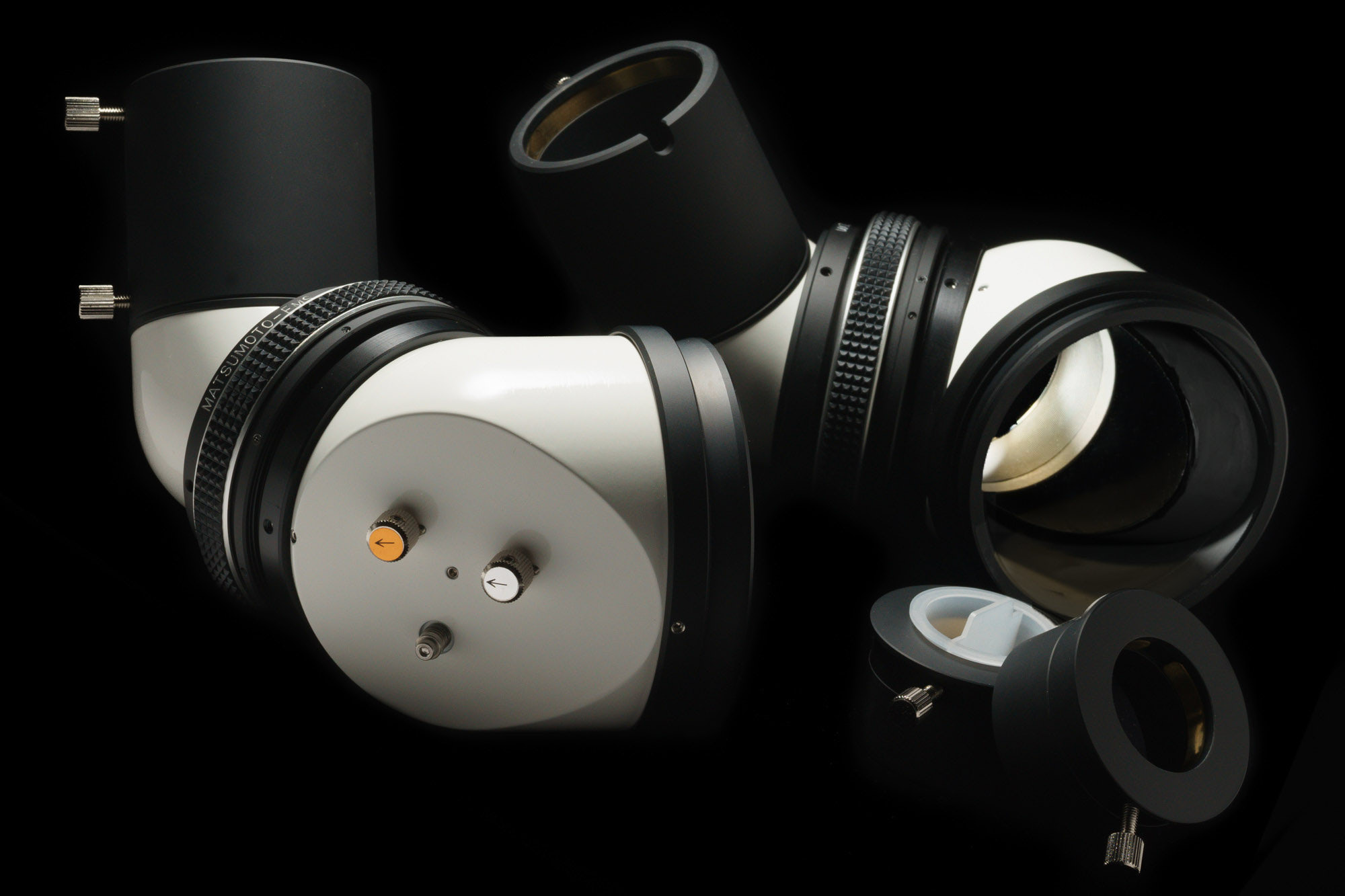


I will show the pictorial above to explain the mechanism of X-Y knobs.
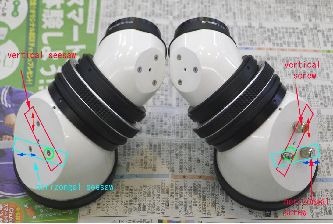
The three screws on the left EMS (first) housing are the first step to understand the X-Y adjusting mechanism on the right EMS. In the case of the left EMS, vertical or horizontal image shift can be caused by turning a pair of the screws at a time, with the green circled screw in common. Note that all of the three screws are pull ones. and the single center set screw is the pushing one to adjust the height of the mirror surface. So, if you replace the green circled pulling screw for a pulling mechanism by a coil spring you can move the image in the X(blue) and the Y(red) directions respectively by each single knob.
ここでX-Yノブのご説明をしておきます。 まずは、左のEMSの第一ユニットを見てください。 3つのプラスネジが右の同ユニットと鏡対称配置になっていることにお気付きになると思います。 赤または青の矢印で代表するネジと、共通に使用する緑の円のネジを同時に回すことで、左のEMSもイメージをX〈青)-Y〈赤)方向に調整できます。(←皆さんに推奨しているのでなく、原理の説明のためにご説明していますので、誤解のないように^^;)3つのプラスネジは全て引きネジ(スケアリング調整用)であり、中央のセットビス(イモネジ)だけが押しネジで、ミラー面の高さが調整できる(センタリング調整用))構造になっています。
つまり、3つの引きネジを、EMSの原理に基いてうまく配置すると、2本ずつのネジの調整で、X-Y方向にイメージを独立的にシフトできるようになります。 そこで、緑の円のネジを、スプリングで常に引っ張るメカに交換すると、残る2本のネジだけで独立的にX-Y調整が可能になるわけです。 それが、右のEMSの第一ユニットのX-Y調整機構なのです。 ご理解いただけましたでしょうか。 何年もEMS-BINOを使われながら、何を思ったのか、「ノブが1個脱落しています!」と慌てて連絡して来られる方が少なくありません。^^; ノブはX用とY用の2本しかありませんので、覚えておいてください。 それを実現するために多大なエネルギーを投入して来たのですから・・・。
I am adding the diagram because the former image seems to be difficult to understand.
当初の説明図が分かりにくいようなので、追加の図を作成しました。(2025,2/18)
ネジの操作は2本ずつセットで行う、ということです。シーソーの原理なので、片方を締めるためには、相手のネジを緩める必要があります。下にシーソーの絵を挿入しますね。
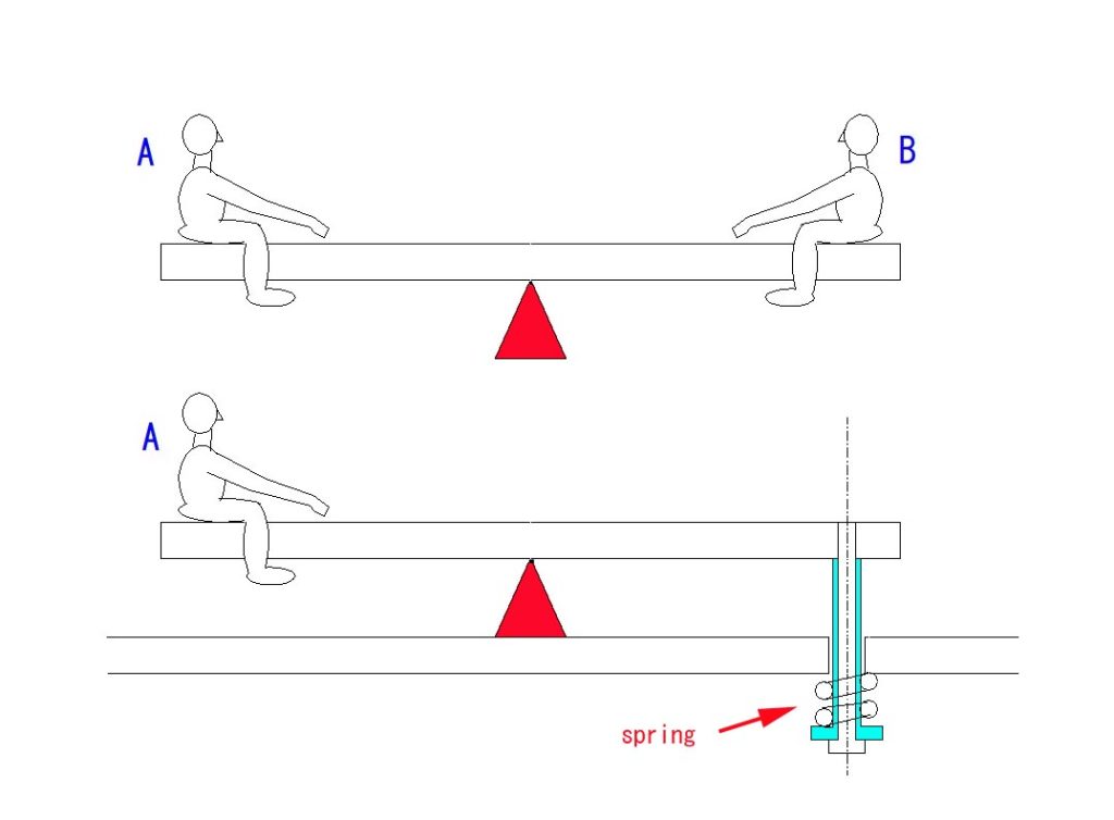
右のEMSは、共通ネジがスプリング機構に替わっているので、一つのノブだけでXもしくはY方向の調整が可能になっています。しかし、原理は左のEMSと同じです。(EMS-UXLの場合)
シーソーの支点に相当する上手の赤い▲ですが、EMSの図の中央のセットビス(イモネジ)に触ると、この支点の高さ自体が変わってしまい、収拾がつかなくなるので、それに触れるのは厳禁です。